-40%
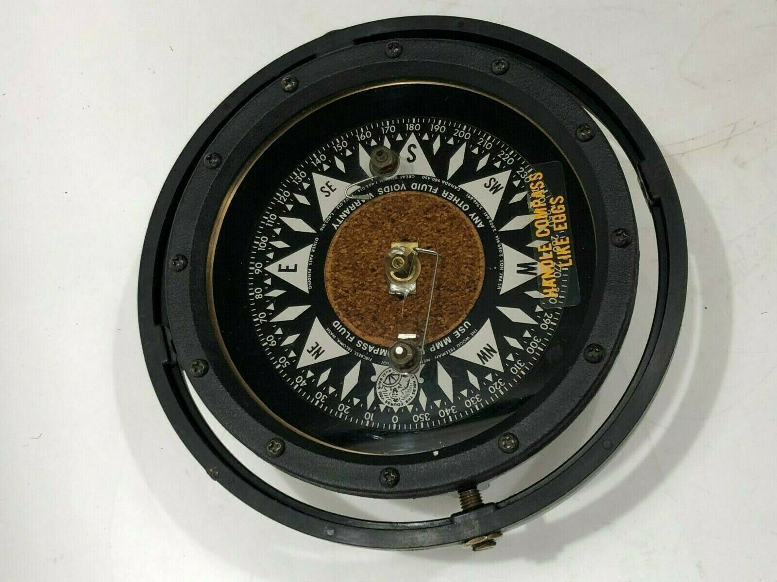
Wood Freeman Autopilot Metal Marine Nautical Compass and Base
$ 57.55
- Description
- Size Guide
Description
Wood Freeman Compass and base can be used with Model 11 or 15 Auto Pilot...or compass could be separated from base and mounted independently as beautiful and accurate ships compass
The following text is from the original Owners Manual printed sometime after the companies inception in 1934 and is included for entertainment only and has no bearing at all on on what is included with this auction
THE METAL MARINE PILOT
Automatic Steering
"It holds the course you give it"
The Automatic Electric Steering Device for " Powered Boats and Vessels of All Sizes
DEPENDABLE, SIMPLE TO OPERATE
Since 1934, when the first METAL MARINE PILOT was manufactured and sold, it has proven to be a dependable mechanism giving years of trouble-free service and requiring little if any upkeep.
Today thousands of vessel owners are getting continuous satisfactory service from their Pilots, and many of them regard i as the greatest advance in efficient operation since engines replaced oars and sails.
The difficulties of holding a powered vessel on a steady course by hand steering, especially under foul weather conditions, are well known to every vessel owner. The installation of a Wood Freeman METAL MARINE PILOT over-comes these difficulties.
It is designed to operate on a very small amount of power, taken from the existing electrical system of the vessel. It is furnished for direct current systems in 6, 12, 24, 32 and 110 volts. A rectification unit for 110 volt A.C. system is available. Normal power requirements for a vessel with average steering mechanism is from 50 to 75 watts—about the equivalent of an ordinary light bulb. Vessels having stiff or sluggish steering mechanism may require a maximum of 150 watts input to the METAL MARINE PILOT.
The Pilot has three principal parts. Compass Unit (the. brain). Relay Unit (the nerve system) and Motor Unit (the muscles). It is furnished complete with one 8-inch sprocket for the steering wheel, all necessary chain and small sprockets for a standard installation, a pair of compensating magnets for the compass, and complete installation and servicing directions. When the Pilot is attached to the electrical system of a vessel, it furnishes the necessary motive and directive power to hold the vessel on a given course, without further aid from human hands. The METAL MARINE PILOT is designed specifically for simple and easy installation. Thousands of our customers, by carefully reading and following our printed instructions, have installed their own Pilots successfully.
OPERATION After it has been properly installed in accordance with our directions, there are only three simple steps to start the METAL MARINE PILOT on its steering task: 1. Turn on relay unit switch and allow the Pilot to run free until it begins to oscillate with short swings.
2. Set vessel on desired course.
3. "Engage clutch on motor unit.
c The vessel will remain on this course until you changy it. Changing course is accomplished by one of two methods:
1. a. Disengage clutch.
b. Swing vessel to new course by hand steering and steady on course.
c. Re-engage clutch. OR:
2. a. Disengage clutch.
b. Move wheel in desired direction of turn one spoke.
c. Re-engage clutch immediately. (The vessel will swing to a new course and hold steady with no further attention.)
d. Note number of degrees course changed with one spoke of wheel movement. This calibration can be used for future changes of course as vessel will always change course same number of degrees per spoke.
The Model 42 includes all the remote control features of the Model 63 Electric Steerer. Model 42 manual operation is the same as the above except that steering wheel stops when Pilot is ready to hold the course. For details of remote control operation see description of Model 63 Electric Steerer.
COMPASS UNIT
The COMPASS UNIT furnishes directing impulses to the Relay Unit by means of its sensitive internal contacts. (v. S. Patent No. 2089914). (Others pending). The Compass Unit should be mounted at the following distances from the objects listed.
24 in. from large iron mass (winch or engine).
24 in. from Motor Unit.
30 in. from Steering Compass
12 in. from end of horizontal or vertical iron rod.
18 in. from Relay Unit.
On steel vessels,
30 in. from vertical and
24 in. from horizontal plates.
A mechanical "follow-up" between the Compass and Motor Units is provided, either chain and sprocket (Model 11), or flexible shaft drive (Models 15 and 42). This mechanics linkage informs the compass of the rudder position at all times and allows the compass unit to provide a correction proportional to the amount the vessel is off course. In order to protect the Compass Unit on Model 11 from water and mechanical damage, it should be enclosed in a suitable cabinet aboard the vessel. (If an exposed mounting position is necessary, The Compass Bowl Cover should be ordered as an accessory. On Models 15 and 42 Pilots the Compass Unit enclosure is standard equipment).
It is necessary to have proper gear ratio in the base of the Compass Unit to obtain the best steering on your vessel. Therefore, please specify the number of turns of the steering wheel from Hard-over to Hard-over (90 degrees of rudder swing). when ordering your Metal Marine Pilot. The Compass Base sprocket must be installed on the forward side of the compass base on chain drive models. If the installation demands that the sprocket be on the aft side, a special base (left hand base) will be furnished at no additional charge if the substitution is request (with the original order. This precaution is not necessary with the Flex-drive models (Models 15 and 42). Two magnets are supplied with which to compensate the pilot compass. Compensation is strongly recommended if the pilot compass differs from the corrected steering compass by more than 5 degrees on any heading.
RELAY UNIT
The RELAY UNIT is enclosed in a gray crackle, galvanized steel box. Directional signals from the compass are amplified and used to control a mercury contact relay which in turn controls the electric motor of the motor unit. Electrical cables connecting the Relay Unit to the other components are furnished and are extremely simple to connect. The power cable and cable to compass urea are each 6 ft. long (12 ft. on Model 42). The power supply for the Pilot is furnished to the Relay Unit from the vessel's source of electrical power and no "B" batteries, vibrators or motor-generators are necessary. Transistorized circuits are used on 6, 12. 24 and 32 volt models.
MOTOR UNIT
The gear-housing and clutch assembly are of corrosion resistant bronze. The internal expanding clutch provides rapid positive action under all operating conditions. It may be adjusted to limit torque on steering wheel. The
clutch drum carries 2 sprockets; one drives the steering wheel sprocket through a # 41 roller chain. The other drives the limit switch.
A special series wound motor driving a spur reduction gear system provides ample power for all normal steering. All motor units are equipped for limit switches. The limit switch assembly may be purchased as an accessory either at the time of Pilot purchase or later. Limit Switches are standard equipment on the Model 42 and the Model 63 Electric Steerer
Motor Units are mounted on varnished plywood bases. Additional holes for mounting are easily drilled as necessary.
Cast metal bases are available on special order. (See accessory list.)
An inexpensive, thoroughly reliable "hunting" type pilot, designed for years of continuous service.
Model 11
Pilot with Compass Bowl Cover added. (A recommended accessory in damp installations).
Features:
• Most accurate steering of any Pilot regardless of price.
• Chain drive follow-up between Compass and Motor Unit.
• Built-in Limit Switch provisions.
• Chain and sprockets furnished.
• Positive action friction clutch, torque limiting.
• Dodger available at slight extra cost.
• Full Remote Control steering, (Model 63) is an accessory available at time of purchase or may be added later.
• Transistorized in all voltages except 110 volt 1). C.
• Available in 6, 12, 24, 32 and 110 Volt D.C.
Includes: Compass Unit (compass bowl cover optional — at extra cost). Relay Unit and connecting cords Motor Unit (Limit Switch assembly optional at extra cost). 50 Tooth-8 in. sprocket for steering wheel shaft. (30, 24, 20 tooth optional, at no extra cost). Chain-2 lengths 614 ft. each, # 41 Blued Steel). Sprockets-16 tooth and 10 tooth. Magnets-2 for compensating compass. Screws for mounting compass base. 1 set Installation and Servicing Instructions.
MODEL 15
A "Hunting" type Pilot with completely housed Com-pass Unit, flexible-shaft driven, for convenient installation.
Features:
• Accuracy of steering unexcelled. Compass Unit completely enclosed in moisture proof housing.
• Flexible shaft follow-up drive between Motor Unit and Compass Unit allows maximum ease of installation.
• Built-in Limit Switch provisions (Limit Switch shown installed.)
• Positive action friction clutch (torque limiting).
• Dodger available (slight extra cost).
• Full Remote Control steering (Model 63) is an accessory available at time of purchase or may be added easily later.
• Transistorized in all voltages except 110 volt D.C.
• Available in 6, 12, 24, 32 and 110 volt D.C.
Includes: Compass Unit (completely housed). Relay Unit and connecting cords. Motor Unit (Limit Switch assembly optional at extra cost). 50 Tooth-8 in. sprocket for steering wheel shaft. 30. 24. 20 tooth optional, at no extra cost). Chain-2 lengths 61/4 ft. each, # 41 Blued Steel. Flexible Shaft and Fittings. 6 ft. long. Magnets-2 for compensating compass. 4 Screws for mounting Compass Base. 1 set Installation and Servicing Instructions.
MODEL 42
A deluxe "Non-Hunting" type Pilot with full remote control.
Features:
• Steering wheel moves only when vessel is off course. Does not continually oscillate.
• Very accurate steering under all sea conditions.
• "Weather Control" on compass adjustable for sea conditions.
• Complete remote control includes dodging, circling, "course memory" maneuvering, and course changing from any number of remote stations.
• Positive acting friction clutch, torque limiting.
• Built-in Limit Switches are standard equipment.
• Completely enclosed weather proof Compass Unit.
• Flexshaft driven compass for maximum ease in installation.
• Dynamic braking system positively positions steering wheel.
• Transistorized in all voltages except 110 volt D.C.
• Available in 12, 24, 32 and 110 volt D.C. Includes: Compass Unit (completely housed). Relay Unit and connecting cords. Motor Unit. Limit Switch assembly (installed on motor unit). Solenoid (for course changing, installed on motor unit). Remote Control Handle (water proof) 50 ft. cord standard—greater length optional at additional cost. Sprocket-50 tooth, 8 in. sprocket for steering wheel shaft. (30, 24, 20 tooth optional, at no extra cost.)
Chain-2 lengths 6 1/4 ft. each. # 41 Blued Steel. Magnet-2 for compensating compass. 1 set Installation and Servicing Instructions. Flexshaft 6 ft. long with fittings. (Other lengths on special order.)


